
CUSTOM ASSEMBLY
Custom crimped wire leads and connector assemblies
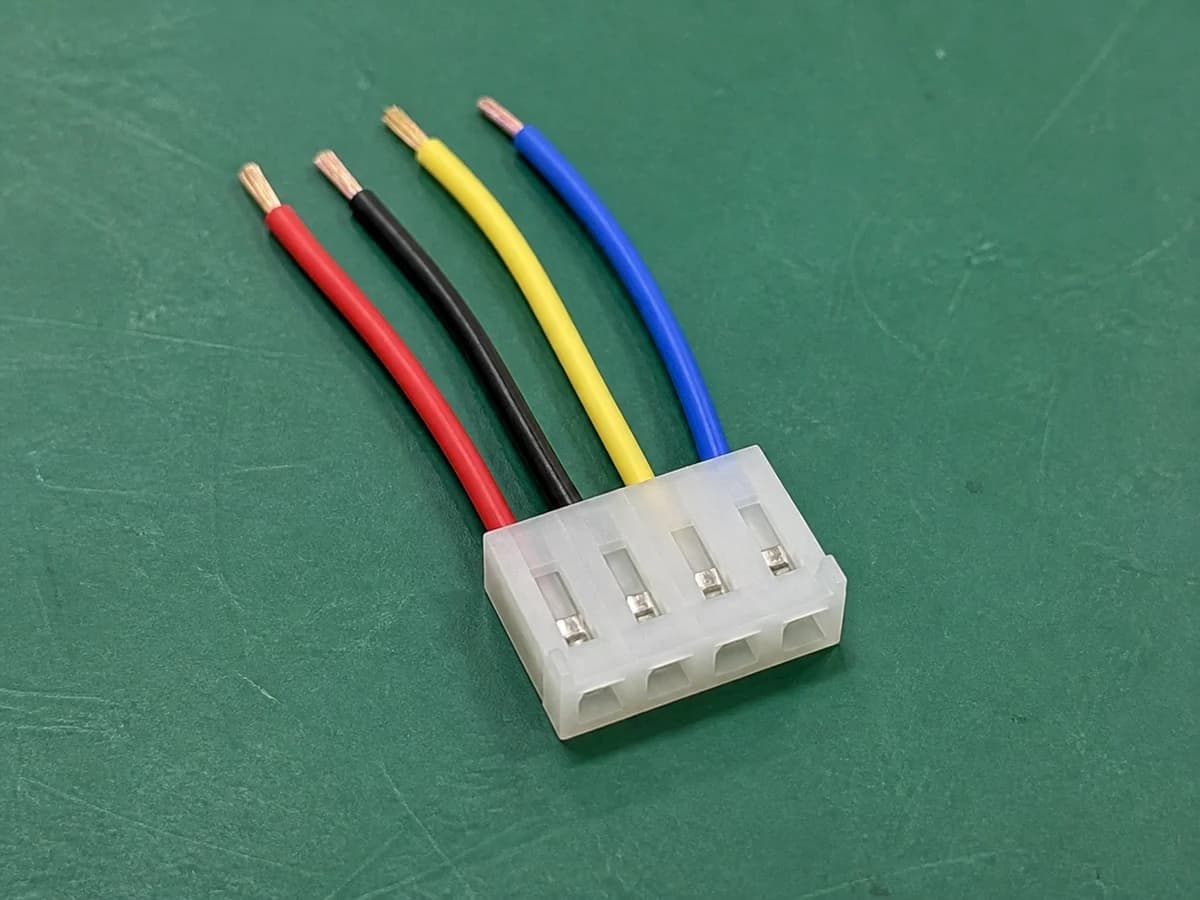
- Use
- Connector leads for downstream equipment assembly.
- Construction
- Crimp contacts seated in a specified housing; opposite ends prepared to drawing.
- Selection focus
- Contact/wire combination, finished length and strip length tolerance.
PRODUCT CONFIGURATION
Interfaces, construction and specifications
Match the assembly type first, then confirm project values. These configuration details guide selection; the approved drawing defines final materials, dimensions and ratings.
- Interfaces & terminations
- Customer-specified crimp housing and contacts; confirm pitch and mating part from drawings.
- Wiring & dimensions
- Pinout, occupied positions, wire colours and finished lead lengths.
- Assembly construction
- Crimped leads with stripped, tinned or terminated opposite ends, as specified.
- Conductor & materials
- Specify conductor size in AWG or mm², conductor construction, insulation and jacket part numbers. Selection must match the terminals; see the material guide below.
- Temperature & validation
- State operating temperature and fixed or moving installation. Assembly ratings, test conditions and records depend on the selected materials and construction.
Project scope and product notes
Crimp-terminated leads with customer-defined housings and opposite-end preparation. Provide the specified housing, contact and mating part numbers to confirm interface fit and termination requirements. Start with a drawing, sample photos or an existing assembly brief to identify the interface, wiring and open questions before the quotation scope is confirmed.
The image illustrates an assembly type. Confirm the interface, positions, length and inspection for the project; undecided RFQ details can remain open.
Additional product technical notes
- Interface review
- Provide the specified housing, contact and mating part numbers to confirm interface fit and termination requirements.
- Customization
- Confirm pinout, wire gauge, colors, length, exit direction and end preparation for the project.
- Inspection scope
- Define sample and production requirements for continuity, polarity, contact retention and visual inspection.
APPLICATIONS
FAQ
What defines the crimp termination?
Provide the housing and contact part numbers, conductor and insulation sizes, and applicable terminal specifications. Agree crimp inspection and any pull-force requirements for the selected combination.
How should the opposite wire ends be specified?
List finished wire length, strip length and tolerance, and whether ends remain stripped or receive a further termination. Include wire identification and the intended downstream assembly process.
REQUEST A QUOTE
Send the requirement for Crimped Connector Lead Assemblies
Send the information you have. Mark undecided details as open; the first review identifies what is needed for quotation or sampling.
Information useful for this assembly
- Application and installation space
- Interface part numbers, or mating-face and wire-entry photos with dimensions
- Pinout, wiring, length and end preparation
- Quantity tiers; mark undecided details as open
- Sample and production tests, identification and packaging