Compact board-to-wire harnesses
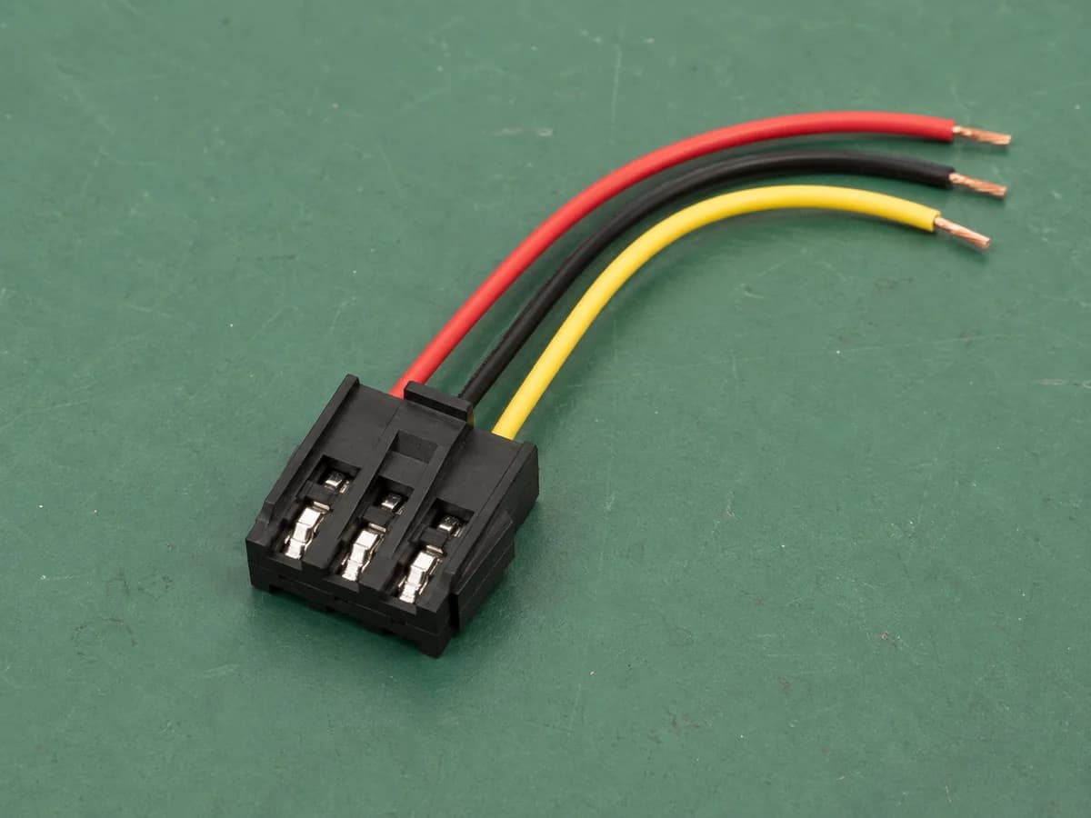
Provide the mating board-side part, occupied cavities, pinout, wire size, finished length and installation direction. Appearance or a catalog family name does not replace a wiring definition.

CONNECTOR INTEGRATION
Board-to-wire leads and wire-to-wire assemblies built around your specified interface. Send the mating connector, pinout, wire length and quantities for review.
PRODUCT OVERVIEW
Connector assemblies are developed around the interface, mechanical constraints, electrical requirements, and assembly process of the finished product.
ASSEMBLY FORMATS AND RFQ INPUTS
Organize the interface, wiring and installation requirements for your assembly. Include mating part numbers, material requirements and critical dimensions so fit and supply options can be reviewed against drawings and samples.
Provide the mating board-side part, occupied cavities, pinout, wire size, finished length and installation direction. Appearance or a catalog family name does not replace a wiring definition.
Define the viewing direction and pin numbering for both rows, with the mating interface and installation clearance. Confirm fit against drawings and samples, not housing appearance.
Specify cable diameter, exit direction, clearance and fixing method, including the panel opening or enclosure interface. Review mechanical support and sealing separately; an overmolded appearance does not establish waterproof performance.
No complete drawing yet? Start with interface photos, pinout information and quantity tiers, and mark undecided items as open.
Send this assembly briefSELECTION AND ACCEPTANCE
A housing name alone does not define a finished lead. Describe the mating interface at one end and the wire preparation or second connector at the other. Use the following checklist to define your custom assembly.
For a PCB connection, identify the header, mating housing, terminal part number, and occupied positions. For a separable wire-to-wire connection, list both mating housings and their contacts, including latch orientation and which ends are supplied. A matching pitch or position count alone does not establish mating compatibility.
Use one row per circuit: End A cavity, wire colour or ID, then End B cavity or end preparation. Add wire size and finished length with its measurement reference. Label the view as mating face or wire-entry side, and mark unused cavities. Specify stripped, tinned, ferrule, or housing-terminated ends. This is a drawing format, not a default pin assignment.
For samples, agree fit with the specified counterpart, latch operation, cavity assignment, length, and end preparation. For production, separate checks on every assembly from lot sampling. Define acceptance criteria for continuity, shorts, terminal seating, and any crimp or pull-force assessment. A continuity result alone does not document every mechanical requirement.
An agreed record can identify the drawing revision, housing and terminal part numbers, lot, method, acceptance limit, result, and disposition. Ask which records are available for the selected assembly and which need additional validation. Keep an approved sample reference with the released wiring table so production is not judged from a photograph alone.
Images show assembly formats. For your order, specify housing and terminal part numbers, materials and required checks; agree the final configuration and acceptance criteria during review.
With a drawing, include its revision, interfaces, pinout and quantity tiers. With photos or a sample, add interface dimensions, wiring information and required tests. Mark undecided items as open.
APPLICATIONS
CUSTOMIZATION & TECHNICAL SCOPE
Housing, terminal, position count, keying, wire or cable exit, retention, and inspection criteria remain project-specific until the part number and drawing are reviewed.
TECHNICAL PARAMETERS
FOR A FASTER QUOTE, PLEASE PROVIDE
FAQ
Yes. Please include the part number, drawing revision, approved alternative requirements, and the required cable or wire specification.
Kitting, identification, and packaging requirements can be included in the RFQ for project-specific review.
REQUEST A QUOTE
Share the drawing, part number, quantity, or application. The engineering team will review the brief and reply with the next questions.