Coiled cables and end terminations
Specify the retracted length, working extension, straight tails, connectors and pinout, including whether the cable moves repeatedly in service. Performance and validation requirements are project-specific.

INDUSTRIAL SYSTEMS
Cable and connector solutions for industrial equipment.
PRODUCT OVERVIEW
Industrial cable solutions are developed around the equipment interface, installation conditions, movement, shielding, labeling, and production documentation required by the OEM.
ASSEMBLY FORMATS AND RFQ INPUTS
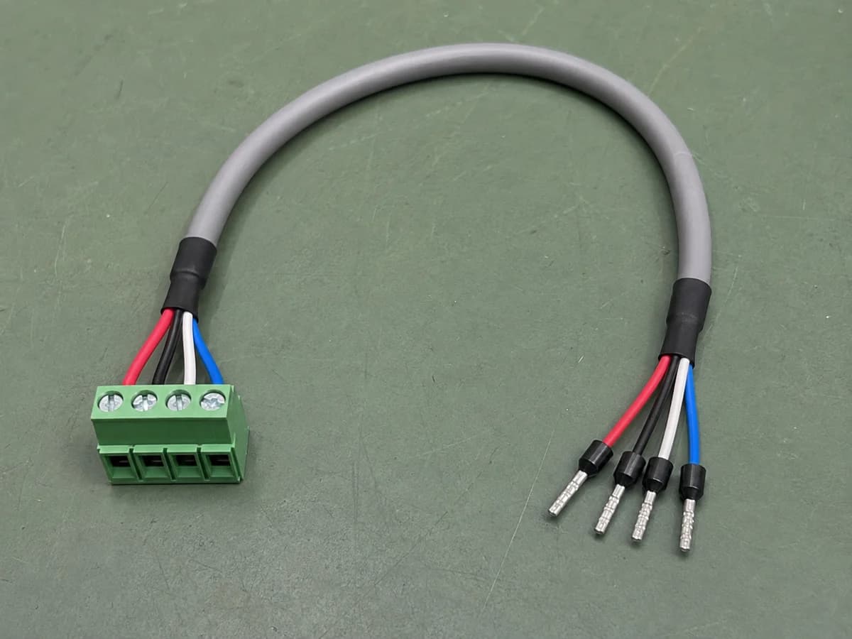
Organize the interface, wiring and installation requirements for your assembly. Include mating part numbers, material requirements and critical dimensions so fit and supply options can be reviewed against drawings and samples.
Specify the retracted length, working extension, straight tails, connectors and pinout, including whether the cable moves repeatedly in service. Performance and validation requirements are project-specific.
Specify cable diameter, exit direction, clearance and fixing method, including the panel opening or enclosure interface. Review mechanical support and sealing separately; an overmolded appearance does not establish waterproof performance.
No complete drawing yet? Start with interface photos, pinout information and quantity tiers, and mark undecided items as open.
Send this assembly briefSELECTION AND ACCEPTANCE
For industrial cable assemblies, start with the equipment interface and how the cable is installed. Fixed wiring, moving equipment and exposed connections need different review information.
Provide the mating connector or terminal information, pinout, conductor requirements and cable length. For M12 connections, include coding and pin count rather than the M12 name alone. Keep power, signal and communication circuits clearly identified in the wiring table.
Show the installed route, support points and available space. For moving applications, state the required bend radius, travel, motion pattern and cycle target for review. Do not assume a cable selected for fixed installation is suitable for repeated flexing.
Identify shield and grounding connections at each end, including any enclosure interface. Describe temperature, oils, cleaning fluids or water exposure where relevant. These are inputs for material and test selection, not capabilities established by a product photograph.
Use samples to check fit, routing, strain relief and agreed electrical requirements in the intended equipment. State which checks apply to every production assembly and which require separate validation. Include drawing revision, labels, quantity tiers and the records required with delivery.
Industrial use does not imply a universal environmental or flex-life rating. Submit the application conditions so the construction and validation scope can be reviewed.
With a drawing, include its revision, interfaces, pinout and quantity tiers. With photos or a sample, add interface dimensions, wiring information and required tests. Mark undecided items as open.
APPLICATIONS
CUSTOMIZATION & TECHNICAL SCOPE
Cable type, length, movement, shielding, grounding, connector termination, identification, and production records are confirmed from the equipment requirement.
TECHNICAL PARAMETERS
FOR A FASTER QUOTE, PLEASE PROVIDE
FAQ
Industrial equipment requirements can be submitted for project-specific review. Drawing inputs, prototype scope, production documentation, inspection requirements, feasibility, and timing are confirmed after the technical brief is received.
Wire markers, labels, part identification, and packaging instructions can be included in the project specification for review.
REQUEST A QUOTE
Share the drawing, part number, quantity, or application. The engineering team will review the brief and reply with the next questions.